How to Maximize Performance with Your AURSINC NanoVNA Antenna Analyzer
Accurate antenna analysis begins with proper calibration and precise frequency settings. Without these, your measurements may lead to unreliable conclusions. For instance, calibration errors can result in a reprojection root mean squared error (RMSE) exceeding acceptable thresholds, compromising accuracy. Maintaining precision ensures consistent and dependable results.
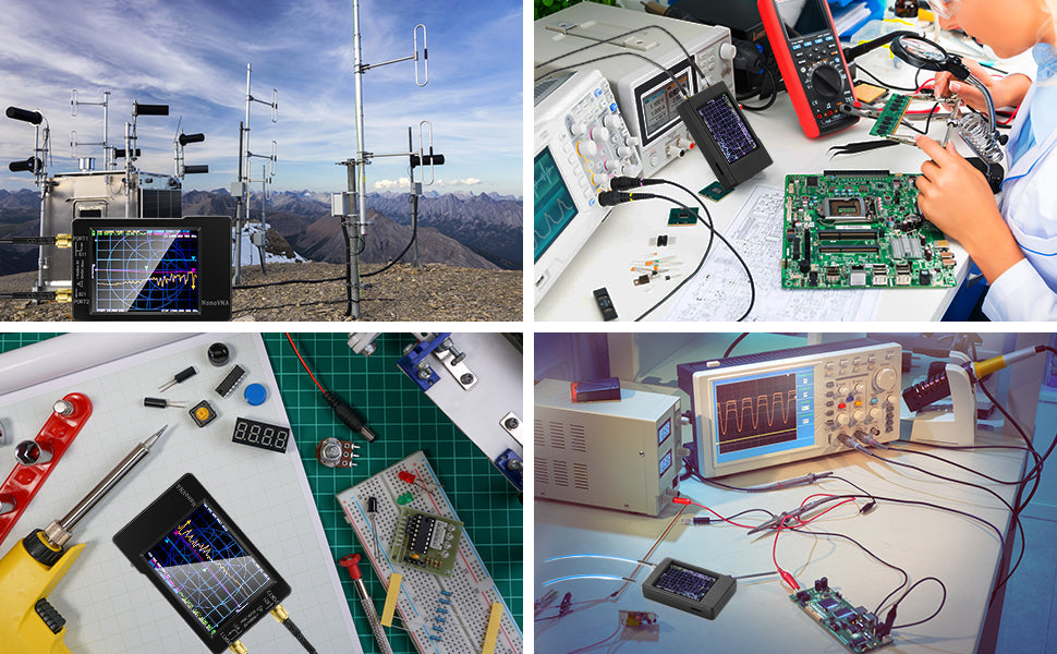
The AURSINC NanoVNA antenna analyzer empowers you to achieve this level of accuracy. This compact yet robust device offers a seamless way to analyze antennas, whether you’re optimizing performance or troubleshooting issues. The NanoVNA H model, with its extended frequency range, further enhances its capabilities, making it indispensable for RF enthusiasts and professionals alike.
Key Takeaways
- Calibration is important for correct measurements. Always follow the steps carefully for good results.
- Pick the right frequency range for your antenna and use. This helps you get clear and useful data.
- Try to get an SWR value close to 1:1. This shows your antenna works well with little power wasted.
- Save your calibration data often. This stops you from losing important settings and keeps your measurements accurate.
- Keep your NanoVNA clean and in good shape. Check it often and store it properly to make it last longer and work better.
Understanding the NanoVNA Antenna Analyzer
Overview of the NanoVNA
The NanoVNA is a compact, handheld vector network analyzer (VNA) that has revolutionized RF and antenna analysis. Designed by edy555, it combines affordability with high performance, making it accessible to both hobbyists and professionals. Its portability, powered by a 3.7V Li-ion battery, allows you to conduct measurements in various environments without being tethered to a power source.
The device's evolution has been driven by community contributions, resulting in enhanced versions like the NanoVNA-H rev3.4 and NanoVNA-H 4. These models achieve a dynamic range of 40dB up to 1.5GHz, offering improved functionality for advanced users. Additionally, the integration of Time Domain Reflectometry (TDR) functionality enables you to measure coaxial cable lengths and pinpoint faults with precision.
Key Features and Capabilities
The NanoVNA antenna analyzer stands out due to its unique features and capabilities. It offers a frequency range of up to 1.5 GHz, with a resolution as fine as 1 Hz. This precision allows you to analyze antennas and RF components with remarkable accuracy. Its dynamic range exceeds -60 dB up to 1 GHz, ensuring reliable measurements across a wide spectrum.
Compared to competitors, the NanoVNA provides exceptional value. While high-end devices like the E5061 Keysight ENA come with a hefty price tag, the NanoVNA delivers comparable performance at a fraction of the cost. Its calibration features, including unknown-thru and adapter-removal methods, further enhance its usability.
Importance of Proper Usage
Proper usage of the NanoVNA antenna analyzer is critical for achieving accurate results. Users often emphasize the importance of following specific instructions to avoid errors. For instance, losing factory calibration data can significantly impact measurement accuracy. Storing calibration values correctly ensures consistent performance and prevents inaccuracies during analysis.
To optimize your experience, always adhere to the recommended calibration procedures. This practice not only enhances the reliability of your measurements but also extends the lifespan of your device. By understanding and applying these principles, you can unlock the full potential of your NanoVNA and achieve precise antenna analysis.
Tip: Always back up your calibration data to avoid losing critical settings.
Calibration Essentials
Preparing for Calibration
Proper preparation is the foundation of accurate calibration. Before you begin, ensure your NanoVNA is fully charged or connected to a stable power source. A low battery can affect the device's performance and lead to inconsistent results. Clean the connectors thoroughly to remove any dust or debris that might interfere with signal transmission. Use a soft, lint-free cloth or an appropriate cleaning solution for this task.
When setting up, choose a stable, interference-free environment. Avoid areas with excessive electromagnetic noise, as it can distort your measurements. Additionally, ensure you have all necessary calibration standards, such as open, short, and load terminations, readily available. These standards are essential for achieving precise calibration.
Recent advancements in calibration methods emphasize the importance of evaluating calibration quality using Relative Standard Error (RSE) and Relative Error (RE). These metrics provide a more accurate assessment compared to traditional correlation coefficients. The table below highlights key findings from updated calibration practices:

Step-by-Step Calibration Process
Follow these steps to calibrate your NanoVNA effectively:
- Connect Calibration Standards: Attach the open, short, and load terminations to the device's ports as prompted by the calibration menu.
- Select Calibration Mode: Access the calibration settings and choose the appropriate mode based on your measurement requirements.
- Perform Calibration: Sequentially connect each standard as instructed by the device. Ensure a secure connection to avoid errors.
- Save Calibration Data: Once the process is complete, save the calibration data to the device's memory. This step ensures consistent performance during future measurements.
Tip: Always label and store your calibration standards properly to prevent contamination or damage.
Understanding the Smith Chart and SWR
The Smith chart is a vital tool for understanding and optimizing antenna performance. It provides a graphical representation of impedance and admittance, helping you visualize how these parameters change across a frequency range. By using the Smith chart, you can determine whether a load is capacitive or inductive and assess the complexity of impedance matching at different frequencies. This makes it an indispensable resource for RF engineers and enthusiasts alike.
In antenna calibration, the Smith chart plays a crucial role in impedance matching. It allows you to analyze the relationship between load impedance and standing wave ratio (SWR). SWR measures how effectively your antenna matches the transmission line. A lower SWR indicates better matching, which minimizes power reflection and maximizes signal efficiency. By plotting measurements on the Smith chart, you can compute the input impedance of your antenna and identify areas for improvement.
The connection between SWR and the Smith chart is fundamental. The concept of SWR influenced the development of the Smith chart, which visually represents standing wave ratios. This graphical interface helps you design impedance-matching networks and determine feed-point impedance based on transmission line measurements. With this information, you can fine-tune your antenna for optimal performance.
To use the Smith chart effectively, you need a basic understanding of AC circuit theory and transmission-line theory. These principles help you interpret the chart and make informed decisions during calibration. By mastering the Smith chart and SWR, you can enhance your antenna's efficiency and ensure reliable communication.
Tip: Always aim for an SWR value as close to 1:1 as possible. This ensures minimal power loss and maximum signal strength.
Frequency Settings Optimization
Selecting the Right Frequency Range
Choosing the correct frequency range is essential for accurate measurements with your nanovna antenna analyzer. The optimal range depends on several factors, including the type of antenna, environmental conditions, and application requirements. Following verified guidelines ensures reliable results and prevents unnecessary recalibrations.
When selecting a frequency range, always consider the antenna's intended use. For example, antennas designed for shortwave communication may require a lower frequency range, while those for cellular networks operate at higher frequencies. By aligning the frequency range with your specific application, you can achieve precise and meaningful results.
Adjusting for Different Antenna Types
Different antenna types require unique adjustments to ensure accurate analysis. The nanovna antenna analyzer allows you to fine-tune settings for various designs, including dipole, Yagi, and loop antennas. Each type has distinct characteristics that influence its performance across frequency bands.
The analysis procedure in IONSUM, based on the output of the IONCAP prediction method, was developed by the VOA to determine which single-frequency band will be most suitable under 'averaged' conditions for a particular service from one transmitter site to a target reception area. The Committee understands that the VOA recognizes the need to supplement the results from IONSUM with additional data from IONCAP regarding the extremes of ionospheric conditions and their statistical distribution.
For instance, a dipole antenna typically performs well in a narrow frequency range, while a Yagi antenna offers better directionality and gain. Adjusting the analyzer's settings to match these characteristics ensures accurate impedance and SWR measurements. Always consult the antenna's specifications and operating conditions to make informed adjustments.
Practical Tips for Antenna Analysis

Tuning Antennas for Best Performance
Tuning your antenna is essential for achieving optimal performance. Start by identifying the desired operating frequency range for your application. Use your nanovna antenna analyzer to measure the antenna's impedance and standing wave ratio (SWR). Aim for an SWR value close to 1:1, as this indicates minimal power loss and maximum signal efficiency.
Adjust the antenna's length or position to fine-tune its resonance. For example, shortening or lengthening a dipole antenna can shift its resonant frequency. Always make small adjustments and remeasure to ensure accuracy. If your antenna includes adjustable components like capacitors or inductors, use these to refine impedance matching further.
Tip: Keep a log of your adjustments and measurements. This practice helps you track changes and identify the optimal configuration for your antenna.
Optimizing Coil Positions
Proper coil positioning plays a critical role in enhancing signal characteristics. When working with antennas that include coils, such as helical or loop designs, ensure the coils are positioned to minimize interference and maximize efficiency. Use your nanovna antenna analyzer to measure the impact of coil adjustments on impedance and SWR.
Enhancing Signal Quality
Improving signal quality ensures reliable communication and reduces interference. Start by selecting antennas with higher gain specifications to focus energy into narrower beams. This approach extends range and improves signal strength. Optimize the antenna's placement and orientation to minimize obstructions and maintain a clear line of sight.
Practical tips for enhancing signal quality include:
- Improving communication range to maintain connectivity over greater distances.
- Reducing interference and dropouts for clearer communication.
- Ensuring consistent performance regardless of device orientation.
- Lowering power consumption by reducing the energy required for communication.
- Minimizing noise from nearby circuitry to boost receiver sensitivity.
Upgrading to advanced technologies like phased array or beamforming can also dynamically adjust signal direction, further enhancing performance. Use your nanovna antenna analyzer to verify improvements and ensure your adjustments yield measurable results.
Note: Regularly inspect your antenna and its connections for wear or damage. Even minor issues can degrade signal quality over time.
Troubleshooting the NanoVNA Antenna Analyzer
Resolving Software Issues
Software issues can disrupt the functionality of your NanoVNA, but resolving them is straightforward with the right approach. Start by ensuring your device runs the latest firmware version. Updated firmware often includes bug fixes and performance enhancements. Visit the official NanoVNA community page or repository to download the latest version. Follow the instructions carefully to avoid installation errors.
If the device freezes or displays unexpected behavior, perform a soft reset. This action restores the device to its default state without erasing calibration data. For persistent issues, consider a factory reset. However, back up your calibration settings before proceeding.
Tip: Use diagnostic tools available in the NanoVNA software to identify and resolve specific errors. These tools can help pinpoint issues like corrupted data or communication failures.
Addressing Incorrect Readings
Incorrect readings can stem from various factors, including environmental interference and improper calibration. To address these issues, follow these steps:
- Ensure the device is calibrated correctly. Use open, short, and load standards to perform a full calibration.
- Retune the device if SWR readings fluctuate due to environmental changes.
- Add ferrite beads to cables to reduce spontaneous tuning issues caused by electromagnetic interference.
- Check for common-mode currents by altering the feedline geometry during measurements.
Users have reported that switching motor polarity or using diagnostic modes can resolve errors like "Motor Fail No Load." These methods highlight the importance of troubleshooting techniques tailored to specific scenarios.
Note: Always measure under conditions similar to those specified in the antenna's datasheet for accurate results.
Managing Hardware Limitations
The NanoVNA, while highly capable, has limitations due to its compact design. To manage these effectively, focus on proper calibration and measurement techniques. Verify calibration by connecting a 50-ohm load and observing the VSWR across frequencies. A 1:1 VSWR indicates accurate calibration. If discrepancies arise, recalibrate the device and ensure the environment is free from interference.
Additional tips for managing hardware limitations include:
- Double-check calibration with a known 50-ohm load and run a frequency sweep.
- Test for high ripple in measurements by adjusting the feedline geometry.
- Use the device within its optimal frequency range to avoid performance degradation.
By understanding and addressing these limitations, you can maximize the performance of your NanoVNA and achieve reliable results.
Calibration and frequency settings are the foundation of accurate antenna analysis. By mastering these essentials, you can unlock the full potential of your nanovna antenna analyzer. Apply the tips shared in this guide to fine-tune your antennas and enhance signal quality. This device offers unmatched precision and versatility, making it an indispensable tool for RF enthusiasts. Whether you are a hobbyist or a professional, the NanoVNA empowers you to achieve reliable results and optimize performance with confidence.